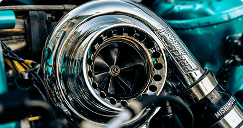
Matching a turbocharger to a marine diesel engine depends on four variables: boost pressure, air-to-fuel balance, exhaust flow efficiency, and correct sizing against engine horsepower. Technicians and vessel operators who treat these as fixed reference points avoid costly guesswork. The key factors in matching turbochargers to marine diesel engines also include the consequences of a mismatch, compressor and turbine A/R ratio specifications, single versus multi-turbo and two-stage configurations, and hands-on verification before installation. Each element influences how reliably the engine delivers power at continuous load. A unit that suits the rated power curve protects fuel economy and durability across long voyages.
Key Factors in Matching Turbochargers to Marine Diesel Engines

Horsepower measurement is the starting point for any turbo selection. A technician reads the engine's rated horsepower and operating profile first, then matches the turbo's flow capacity to that figure. Flow capacity, not housing size alone, decides whether the unit meets the rated figure. This step anchors every later decision. A compression ignition marine diesel engine rated for continuous duty needs a unit sized for that duty, not for a brief sprint. The rated power curve, the propeller load line, and the expected engine rpm band together define the airflow the turbocharger must supply. Multi-cylinder arrangements add one more check: both banks must see consistent turbo behavior, so airflow and fuel burn stay even across cylinders.
Horsepower and Engine Specifications
The rated horsepower figure tells the selector how much air mass the engine must ingest at full load. Marine diesel engines run under continuous high load, often for days at a time. Selection therefore prioritizes stable boost at full load rather than peak response alone. A unit that spools instantly but sags at sustained load will hurt fuel consumption and durability. Stable boost pressure during long-distance navigation supports combustion efficiency, holds power steady, and keeps exhaust temperatures predictable. Power stability matters more than a sharp throttle response. A turbocharger sized for peak response alone often runs hot at cruise, and heat shortens bearing life. Fuel consumption rises when boost falls off at cruise. Operators who log load profiles give the selector better data than a nameplate rating alone. Regulators treat turbocharging mainly as an emissions-control enabler. The EPA notes that turbocharging enables aftercooling, which has strong potential to control NOx emissions in marine diesel engines. The agency does not assume turbocharging by itself improves fuel economy. That distinction matters: sizing choices affect emissions compliance directly and combustion quality indirectly.
Turbo Size and Component Selection
Four core components deserve evaluation: the compressor, the turbine, the trim, and the A/R ratio. Supporting parts matter too:
· Compressor and turbine wheels increase airflow for efficient combustion.
· Intercoolers and wastegates regulate air temperature and boost levels.
· Bearings and seals maintain smooth rotation and prevent oil leaks.
Housing A/R ratios determine airflow efficiency and responsiveness across the speed range. Trim sets how much flow passes through a given housing, so the two choices work together. The compressor side governs intake air delivery; the turbine side governs how much energy the exhaust surrenders. Example marine specifications pair a compressor A/R of 0.95 with a turbine A/R of 1.19. The operating profile shapes the final choice:
Operating profile characteristic | Turbocharger selection | Rationale |
Most time at steady loads | 0.75 compressor housing (A/R) | Fast spool-up without lag; strong airflow under continuous operation |
Long durations at 80–90% throttle | 1.03 turbine ratio (A/R) | Exhaust flow efficiency and temperature control; cooler exhaust temperatures |
Continuous fixed-RPM operation | 1.03 turbine housing | Stable exhaust temperatures; prevents thermal overload |
The key factors in matching turbochargers to marine diesel engines converge on these component choices. Engine performance matching on marine diesel engines rewards this discipline. Correct intake flow and stable boost protect full-load power output and hold fuel consumption in check across long voyages. Each marine diesel engine platform differs in flange patterns, so physical verification closes the process: confirm mounting flange patterns, inlet and outlet orientation, and oil feed and return layout before ordering.
Consequences of a Mismatched Turbo
Improper turbo sizing shifts every operating variable at once. Boost levels drift from the design target, exhaust gas temperatures move outside the expected band, and cooling efficiency falls away from its rated margin. Horsepower output follows the same curve. A unit that sits outside the correct size band forces the marine diesel engine to work against its own calibration. Long-term durability suffers first at the bearings and the exhaust valves. The emissions angle deserves equal attention. A turbocharger shapes how a compression ignition marine diesel engine burns fuel, and the burn quality decides what leaves the stack. IMO regulations set limits on NOx emissions from marine engines, so a sizing error can push a vessel outside its compliance margin. Neither size is inherently poor. Each one simply fits a different duty profile.
Undersized Turbo Symptoms
An undersized unit reaches boost quickly but cannot hold it at full load. The compressor runs near its surge line, and intake air delivery becomes uneven across the rpm band. Exhaust temperatures climb as the engine fights for air, and the cooling system carries a heavier heat load. Power output flattens at the top end, so the vessel loses speed exactly when the operator needs it. Fuel consumption rises because the engine runs rich under sustained load. This size suits short-run, light-load work where fast response matters more than top-end reserve. Continuous high-load service exposes its limits quickly.
Oversized Turbo Symptoms
A large unit trades response for flow capacity, and the trade often costs more than it returns. A turbo that is too large may create sluggish boost response and improper power curves. The engine lags during acceleration, and the vessel feels heavy through maneuvers. Low-load running keeps the compressor far from its efficient island, so fuel consumption climbs during harbor work and slow transits. Soot loading and wet stacking follow. This size fits engines that spend most of their hours near rated power, where the flow capacity pays back. Operators who mix idle time with full-load passages need a middle ground. Either mismatch compounds over a long voyage, and both raise fuel consumption and stress the hardware.
Reading Compressor and Turbine A/R Ratios
The A/R ratio describes a turbocharger housing in two parts. The A stands for the cross-sectional area of the housing throat. The R stands for the radius from the housing center to that area. A small A/R ratio forces exhaust gas through a narrow passage, so velocity rises and the wheel spins up quickly. A large A/R ratio opens the passage, so velocity drops and flow capacity grows. On marine diesel engines, which run under constant load at cruising rpm, this ratio decides spooling behavior, combustion stability, and safe engine temperatures. A mismatch here causes over-boosting or under-boosting, and both conditions stress the aftercooler and internal components.
How A/R Ratio Shapes Airflow
Housing size changes the character of the turbocharger across the whole speed band. A small turbine housing accelerates exhaust velocity and delivers fast spool with strong low-end boost. A large housing trades that response for high airflow at rated speed and lower backpressure. The table below summarizes the trade-off.
Attribute | Small A/R turbine housing | Large A/R turbine housing |
Exhaust gas velocity | Higher through smaller throat | Lower through larger throat |
Spool-up | Fast, minimal lag | Slower, lazier response |
Top-end airflow | Restricted at high rpm | Strong at high rpm |
Exhaust gas temperature | Higher under load | Lower at peak flow |
Best use case | Low-rpm torque | High horsepower, high rpm |
The compressor side works the same way. A tighter compressor housing raises the turbocharger pressure ratio at lower engine speeds. A wider housing supports greater intake mass flow near full load.
Example Marine Specifications
Detroit Diesel 92 Series marine aftercooled engines specify a compressor housing A/R of 0.95 and a turbine housing A/R of 1.19. Technicians must match these values to preserve intended spooling and boost behavior. A typical setup for the same series pairs a 0.75 compressor housing with a 1.13 turbine housing. That combination balances low-to-mid rpm response with sustained high-load operation, as seen on twin 8V92 fishing boats. The two sides interact directly. A tight compressor paired with a loose turbine builds boost early and holds power at cruise. A loose compressor with a tight turbine spools late and chokes exhaust flow. Select both sides as one system, then confirm the figures against the engine's rated power curve.
Single vs. Multi-Turbo Matching
A three-phase methodology governs the selection of a single turbocharger for a marine engine. Phase one fixes the engine's air demand from its rated power and load profile. Phase two matches compressor and turbine flow to that demand. Phase three verifies the choice against measured boost and exhaust data. The same logic scales upward when an engine carries more than one unit.
Parallel Turbocharger Configurations
Parallel matching starts with the total air mass the engine requires, then divides that figure across the number of units. Each turbocharger must deliver its share at the same pressure ratio, so the units run as a matched set. Technicians confirm that both banks of a V-engine see equal boost and equal exhaust temperature. Uneven split loading shows up first as a temperature spread between banks. A compression ignition marine propulsion engine with two parallel units also needs balanced wastegate settings, or one unit carries more load than the other.
Two-Stage Turbocharging for Four-Stroke Medium-Speed Diesel Engines
Two-stage turbocharging delivers its largest gains through higher maximum firing pressure and improved gas exchange work. Yanmar's Technical Review reports that between 1960 and 2016 the company cut fuel consumption of its four-stroke medium-speed diesel engines by 50 g/kWh or more, crediting higher Pmax and better gas exchange work, both enabled by turbocharging technology.
The MAN V4x/60CR four-stroke, two-stage turbocharged engine was reported to exceed 50% efficiency, but no specific fuel consumption gain was quantified in the source.
Published figures show the scale of the benefit:
Source (CIMAC 2016) | Engine context | Fuel consumption gain |
Wärtsilä (M. Vaarasto, #191) | Four-stroke medium-speed engine; two-stage turbocharging enabling pressure ratios near 10 and advanced Miller timing | SFOC improvement of 7–9 g/kWh (alongside ~50% NOx reduction) |
ABB (simulation) | High-output engine at 28.5 bar BMEP; two-stage turbocharging vs. sequential single-stage package | About 5 g/kWh SFOC benefit |
Two-stage turbocharging suits four-stroke medium-speed diesel engines that need high pressure ratios. A single-stage turbocharger remains the simpler choice for lower ratings. In two-stroke marine propulsion engines, the electric motor-generator power of an electric turbo compound becomes a key matching factor, and scavenging pressure shapes the match. Two-stage turbocharging also supports advanced Miller cycle timing on four-stroke medium-speed diesel engines. Operators weighing two-stage turbocharging against simpler layouts should compare specific fuel oil consumption across the load band, not at one point. Two-stage turbocharging rewards engines that run near rated power for long periods. Four-stroke medium-speed diesel engines in auxiliary and propulsion duty both benefit. Two-stage turbocharging raises peak cylinder pressure, so component strength must match. Four-stroke medium-speed diesel engines built for high Pmax accept the load. Two-stage turbocharging and scavenging efficiency work together on two-stroke designs. Fuel consumption falls when gas exchange work improves. Two-stage turbocharging remains the strongest lever for fuel consumption on modern four-stroke medium-speed diesel engines.
Matching Boost Pressure to Engine Load
Marine diesel engines run at continuous high load for hours or days. Fuel efficiency and power stability decide whether a voyage pays. A propulsion engine holds a steady load line against the propeller curve. Boost pressure must track that line without surging or sagging. Two-stage turbocharging gives the selector a wider pressure band to work with. A single-stage unit covers a narrower band. Either way, the match must hold across the whole load range, not just at one point.
Air-to-Fuel Balance Under Constant Load
Stable boost pressure keeps the air-to-fuel ratio inside its design window. The air intake system delivers dense charge air, and the compression ignition process burns it predictably. A steady ratio supports combustion efficiency and lowers fuel consumption. Marine diesel engines that see stable boost also hold exhaust gas temperatures in check. Two-stage turbocharging helps here, because the first stage and second stage share the pressure rise. That split keeps the ratio even at part load and at full load. Operators report lower fuel consumption across long passages. Two-stage turbocharging also protects engine efficiency when sea conditions shift the load. A well-matched unit keeps intake charge dense and combustion clean. Two-stage turbocharging supports that goal on medium-speed platforms. Fuel consumption falls when the ratio stays stable. Two-stage turbocharging earns its place on engines that run near rated power for long periods.
Exhaust Flow and Backpressure Limits
Exhaust flow must leave the engine without raising backpressure beyond the design limit. The exhaust manifold collects pulses, and the exhaust system carries them away. A restriction here pushes backpressure up and steals power from the turbine. Two-stage turbocharging changes the backpressure picture, because two turbines in series add flow resistance. The selector must confirm that the combined restriction stays within the engine maker's limit. Two-stage turbocharging rewards careful sizing of both turbine stages. A mismatch shows up as high backpressure at full load and lost power. Two-stage turbocharging also affects how the exhaust manifold feeds each stage. Technicians measure backpressure at the manifold before signing off. Two-stage turbocharging demands that check more than a single-stage layout does. Stable boost and safe backpressure together protect power output and fuel consumption. Two-stage turbocharging ties both goals to correct stage matching.
Practical Verification Before Installation

Verification closes the selection process. A technician confirms the A/R markings, measures the old unit, and compares both against the specification sheet. This step matters most for marine diesel engines under constant load, where a small mismatch compounds over long voyages. Two-stage turbocharging raises the stakes further, because two housings and two stages must each match their design point. A single wrong housing on a two-stage turbocharging system distorts the pressure split between stages. The same error on a single unit distorts the whole boost curve. Either way, the error shows up as lost power and higher fuel consumption.
Confirming A/R Markings Visually
The housings carry their own identification. A technician follows a short sequence to read it:
1. Locate the compressor and turbine housings on the existing turbocharger.
2. Inspect the housings for A/R ratio numbers that manufacturers either stamp or cast onto the surface.
3. Check the specific physical areas of the turbo where these housing measurements are typically found to confirm correct sizing.
4. Compare visual cues — housing shape, inlet/outlet orientation, flange types, and the A/R markings — to verify the old turbo matches the replacement configuration.
Two-stage turbocharging complicates this check. Each stage carries its own compressor and turbine housing, so the technician reads four markings instead of two. A two-stage turbocharging layout also hides the high-pressure stage behind the low-pressure unit, and that placement obscures some castings. Good lighting and a clean housing surface make the numbers legible. Two-stage turbocharging rewards this patience, because a misread marking on either stage throws off the pressure ratio.
Measuring Against the Existing Turbocharger
Markings alone do not settle the match. A technician measures the old unit and records the results:
· Measure the compressor and turbine wheel diameters and note the housing A/R if it is marked on the housing.
· Record inlet and outlet flange dimensions alongside any casting numbers to narrow down the frame family and model.
· Use the assembly number as the most precise identifier, since it ties the unit to an exact build specification including housing A/R.
The assembly number settles most disputes. It links the unit to an exact build, and that build fixes the housing A/R. Two-stage turbocharging systems need both assembly numbers, one per stage. A technician who records only one number leaves the second stage unverified. Marine diesel engines run at steady load for long stretches, so a small bore or flange error grows into a real fault. The intake charge falls short, power drops, and fuel consumption climbs. Two-stage turbocharging magnifies each of these effects, because both stages share the duty. Engine rpm at cruise reveals the drift first. A unit that matches the old dimensions holds its rated boost. Two-stage turbocharging demands that every dimension, marking, and assembly number line up before the new unit leaves the bench.
Service Manuals and Installation Safety
Checking Official Specifications First
The engine maker's service manual remains the final authority on installation. It lists the torque sequence for manifold studs, the oil feed pressure range, and the clearance limits for the turbine shaft. A technician who follows those figures protects the warranty and the hardware. Aftermarket data sheets help with selection, yet they never override the manual. Torque values deserve particular care. An over-tightened flange distorts the housing seat, and a loose one leaks exhaust gas into the engine room. The manual also states the correct gasket type and the break-in procedure for a new turbocharger.
Specifications from the manual also settle the boost target. A technician compares the measured boost curve against the manual's chart before the sea trial. Marine diesel engines tolerate little deviation at continuous load, so the manual's tolerance band defines pass or fail. Two-stage turbocharging adds a second set of figures, one per stage, and the manual lists both. Skipping that check leaves the pressure split unverified.
Safety Precautions for Marine Installations
Engine rooms combine heat, moving machinery, and tight quarters. A technician secures the following before any work begins:
· Lock out the engine and tag the starter circuit.
· Let the exhaust manifold cool fully before contact.
· Ventilate the space and test the atmosphere before entry.
· Wear eye protection and heat-resistant gloves.
Confined spaces raise the risk further. A bilge or a casing between frames traps fumes and limits escape routes. A second person stands watch at the hatch with a radio. Two-stage turbocharging systems place hot components in awkward positions, so the technician plans the lift before reaching in. Marine diesel engines stay hot long after shutdown, and a careless hand near the turbine housing causes a serious burn.
Operators comparing replacement options should note that Kaidi marine applied turbochargers use salt spray corrosion-resistant and seawater-proof materials, a reinforced waterproof and sealed structure, and marine industry certification. The range suits multiple marine engine platforms, including Volvo Penta ship engine systems, and serves commercial vessels, cargo ships, fishing vessels, offshore support vessels, inland river ships, and engineering marine equipment. Correct installation protects boost, power, and fuel consumption across every one of those duties. Two-stage turbocharging layouts benefit from the same care, and turbocharging technology only pays back when the fit is right. Fuel consumption and power both depend on that discipline.
The key factors in matching turbochargers to marine diesel engines come down to four checks. A technician sizes the turbocharger against rated horsepower, confirms matched A/R ratios on both housings, verifies boost and exhaust flow, and cross-checks every figure against the official service manual. Proper matching protects power, fuel consumption, and reliability in constant-load service. These key factors in matching turbochargers to marine diesel engines also support emissions compliance, since intake air temperature and boost pressure strongly affect nox emissions and particulate output. A water-jacketed unit that mirrors the original charging characteristics preserves that power and fuel consumption. Operators should apply these verification steps before they purchase any replacement unit. For application-specific assistance, buyers can contact Kaidi for marine turbocharger inquiries.



 Login